A distributed cache is the backbone of almost every high-scale system. Whether it’s storing session data, reducing database load, or serving real-time leaderboards, systems like Redis and Memcached are ubiquitous. In this guide, we’ll design a scalable, fault-tolerant distributed cache from scratch.
Table of Contents
Open Table of Contents
- Interview Framework: How to Approach This Problem
- Step 1: Clarifying Requirements
- Step 2: Core Assumptions and Constraints
- Step 3: High-Level Architecture
- Step 4: The Hardest Problem - Data Partitioning
- Step 5: Eviction Policies (LRU, LFU, FIFO)
- Step 6: Data Consistency Models
- Step 7: Scaling the System
- Step 8: High Availability and Replication
- Step 9: Handling Edge Cases
- Step 10: Performance Optimizations
- Real-World Implementations
- Common Interview Follow-Up Questions
- Q: Redis is single-threaded. How does it scale to millions of requests per second?
- Q: How do you prevent cache stampede when a hot key expires?
- Q: How would you keep cache and database consistent?
- Q: How do you implement a safe distributed lock?
- Q: How do you handle hot keys and uneven shard traffic?
- Conclusion
- References
- YouTube Videos
Interview Framework: How to Approach This Problem
In a system design interview, when asked to design a distributed cache (like Redis or Memcached), here’s the structured approach you should follow:
- Clarify requirements (5 minutes) - Determine if it’s a simple key-value store or requires complex data types.
- State assumptions (2 minutes) - Define read/write ratios and latency targets.
- High-level design (10 minutes) - Sketch the client, load balancer, and cache nodes.
- Deep dive (20 minutes) - Focus on Sharding (Consistent Hashing) and Eviction Policies.
- Scale and optimize (10 minutes) - Discuss replication, gossip protocols, and TCP optimizations.
- Edge cases (3 minutes) - Thundering herd problem, hot keys.
Key mindset: This is a data-intensive design. Focus heavily on how data is partitioned (sharding) and how memory is managed (eviction).
Step 1: Clarifying Requirements
Questions to Ask the Interviewer
Q: What is the primary access pattern?
- A: Heavy read, heavy write? Assume 90% reads, 10% writes.
- A: What is the specific latency requirement? < 10ms for 99th percentile.
Q: How much data do we need to store?
- A: TB scale? We will need multiple nodes; single node memory isn’t enough.
Q: Do we need persistence?
- A: If a node restarts, should data be recovered? Yes, minimal data loss is acceptable, but durability isn’t primary (it’s a cache, not a DB).
Q: What happens when memory is full?
- A: We need an eviction policy. LRU (Least Recently Used) is standard.
Functional Requirements
put(key, value): Stores data with an optional expiration (TTL).get(key): Retrieves data.- High Availability: System continues to function if nodes fail.
- Scalability: Can add nodes easily to increase capacity.
Non-Functional Requirements
- Low Latency: < 5ms average.
- High Throughput: Handle millions of QPS.
- Eventual Consistency: Acceptable for a cache (vs. strict consistency for a DB).
Step 2: Core Assumptions and Constraints
Let’s do some back-of-the-envelope calculations to size our system.
Traffic Estimates:
- DAU: 100 Million
- QPS: 1 Million requests/second average.
- Peak QPS: 2-3 Million.
Storage Estimates:
- Total Cache Size: ~30TB of hot data.
- Average Object Size: 1KB.
- Memory needed per node: 32GB or 64GB (avoid going too large due to GC pauses in languages like Java, though Redis uses C).
- 30TB / 32GB ≈ 1,000 nodes.
Bandwidth:
- 1M QPS * 1KB = 1GB/second (Network I/O will be a significant factor).
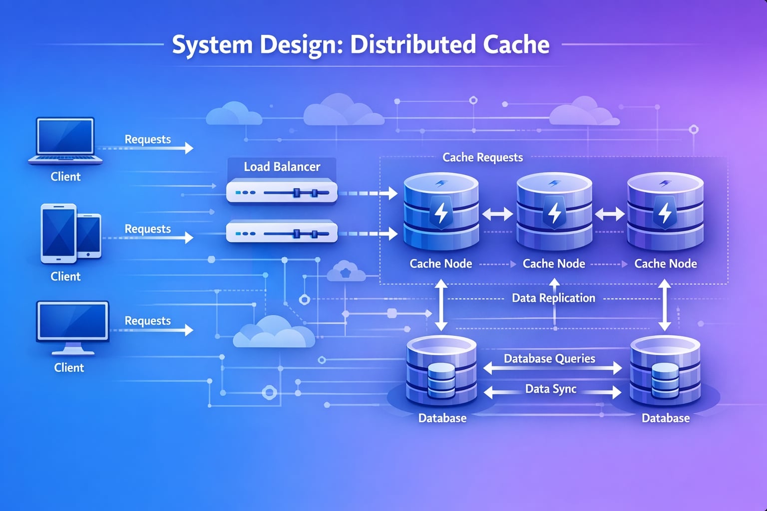
Step 3: High-Level Architecture
I will propose a distributed architecture where the intelligence can reside either in the Client (Client-side routing) or a Proxy (Server-side routing). For this design, I’ll choose Client-Side Routing (like many Memcached deployments) for lower latency (no extra hop), but acknowledge Proxy (like Twemproxy) as a valid alternative for simpler clients.
System Flow Diagram
flowchart TD
    Client[Client App] --> LB[Load Balancer]
    LB --> WS[Web Servers]

    subgraph "Cache Cluster"
    WS -- "Hash(Key)" --> N1[Cache Node 1]
    WS -- "Hash(Key)" --> N2[Cache Node 2]
    WS -- "Hash(Key)" --> N3[Cache Node 3]
    end

    classDef cluster fill:#e1f5fe,stroke:#01579b,stroke-width:2px,color:#000000;
    class N1,N2,N3 cluster;
Data Flow
- Client requests data for “Key A”.
- Web Server (acting as Cache Client) holds a map of the hash ring.
- It calculates
hash("Key A"). - It determines “Key A” belongs to Node 2.
- It connects directly to Node 2 to
GETorPUT.
Why This Architecture?
- Low Latency: Critical for caching. No intermediate proxy hop.
- No Single Point of Failure: If we implement the client cleverly, there’s no central coordinator bottlenecking requests.
Step 4: The Hardest Problem - Data Partitioning
“The most critical challenge in a distributed cache is deciding which node stores which key.”
Approach 1: Modulo Hashing (Naive)
node_index = hash(key) % N (where N is number of nodes)
- Problem: If
Nchanges (node dies or we scale up), almost ALL keys are remapped. The cache essentially flushes itself, causing a massive load spike on the DB (Thundering Herd). - Verdict: ❌ Not acceptable for production.
Approach 2: Consistent Hashing (The Solution)
We map both Nodes and Keys to a circular hash space (e.g., 0 to $2^{32}-1$).
- Ring Topology: Visualize a circle.
- Placement: Hash servers by their IP/ID to place them on the ring.
- Key Lookup: Hash the key. Move clockwise on the ring until you find a server. That server owns the key.
Handling Hotspots: Virtual Nodes
A common issue with basic consistent hashing is non-uniform data distribution (one node gets a huge segment of the ring).
- Solution: Virtual Nodes.
- Instead of mapping “Node A” to 1 point, map it to 100 random points on the ring (“Node A_1”, “Node A_2”, …).
- This statistically ensures data is spread evenly across physical machines.
Step 5: Eviction Policies (LRU, LFU, FIFO)
When memory is full, we must delete items to make room. The algorithm we choose impacts our Cache Hit Ratio.
1. Least Recently Used (LRU) - The Standard
Discards the least recently used items first. Good for recency-based patterns (e.g., breaking news, trending tweets).
Java Implementation (O(1) complexity):
We use a HashMap for fast lookups + Doubly Linked List for ordering.
import java.util.HashMap;
import java.util.Map;

class LRUCache<K, V> {

    class Node {
        K key;
        V value;
        Node prev, next;

        Node(K key, V value) {
            this.key = key;
            this.value = value;
        }
    }

    private final int capacity;
    private final Map<K, Node> map;
    private final Node head, tail; // Dummy head/tail

    public LRUCache(int capacity) {
        this.capacity = capacity;
        this.map = new HashMap<>();

        // Initialize dummy nodes
        head = new Node(null, null);
        tail = new Node(null, null);
        head.next = tail;
        tail.prev = head;
    }

    public synchronized V get(K key) {
        if (!map.containsKey(key)) return null;

        Node node = map.get(key);
        remove(node); // Remove from current position
        addToFront(node); // Move to head (Most Recently Used)

        return node.value;
    }

    public synchronized void put(K key, V value) {
        if (map.containsKey(key)) {
            Node node = map.get(key);
            node.value = value;
            remove(node);
            addToFront(node);
        } else {
            if (map.size() >= capacity) {
                // Evict LRU (item before tail)
                map.remove(tail.prev.key);
                remove(tail.prev);
            }
            Node newNode = new Node(key, value);
            map.put(key, newNode);
            addToFront(newNode);
        }
    }

    private void remove(Node node) {
        node.prev.next = node.next;
        node.next.prev = node.prev;
    }

    private void addToFront(Node node) {
        node.next = head.next;
        node.prev = head;
        head.next.prev = node;
        head.next = node;
    }
}
2. Least Frequently Used (LFU) - Frequency Matters
Discards items with the lowest reference count. Good for stable access patterns (e.g., homepage configuration).
Why it’s harder: An O(1) LFU is complex. A naive approach using a MinHeap takes $O(\log n)$. Efficient Approach: Three Data Structures.
vals: Key -> Valuecounts: Key -> Frequencylists: Frequency -> LinkedHashSet of Keys (Bucket sort style)
import java.util.*;

class LFUCache {
    private final int capacity;
    private int minFreq;
    private final Map<Integer, Integer> vals;
    private final Map<Integer, Integer> counts;
    private final Map<Integer, LinkedHashSet<Integer>> lists;

    public LFUCache(int capacity) {
        this.capacity = capacity;
        this.minFreq = 0;
        this.vals = new HashMap<>();
        this.counts = new HashMap<>();
        this.lists = new HashMap<>();
        lists.put(1, new LinkedHashSet<>());
    }

    public int get(int key) {
        if (!vals.containsKey(key)) return -1;

        // Update frequency
        int count = counts.get(key);
        counts.put(key, count + 1);

        // Remove from old freq list
        lists.get(count).remove(key);
        if (count == minFreq && lists.get(count).isEmpty()) {
            minFreq++;
        }

        // Add to new freq list
        lists.computeIfAbsent(count + 1, k -> new LinkedHashSet<>()).add(key);

        return vals.get(key);
    }

    public void put(int key, int value) {
        if (capacity <= 0) return;

        if (vals.containsKey(key)) {
            vals.put(key, value);
            get(key); // Trigger freq update
            return;
        }

        if (vals.size() >= capacity) {
            // Evict LFU
            int evictKey = lists.get(minFreq).iterator().next();
            lists.get(minFreq).remove(evictKey);
            vals.remove(evictKey);
            counts.remove(evictKey);
        }

        // Add new item
        vals.put(key, value);
        counts.put(key, 1);
        minFreq = 1;
        lists.get(1).add(key);
    }
}
3. FIFO (First In First Out)
Simplest. A Queue. Bad hit ratio because it evicts old but potentially popular data. Rarely used in production caches.
Step 6: Data Consistency Models
Since we have a Database as the Source of Truth, how do we keep the Cache in sync?
1. Cache-Aside (Lazy Loading) pattern
The application logic handles the coordination.
- App checks Cache.
- Miss? App reads DB.
- App writes to Cache.
- Pros: Resilient to cache failure. simple.
- Cons: Stale data window (if DB updates, cache is old until TTL expires).
2. Write-Through
App writes to Cache, Cache writes to DB synchronously.
- Pros: Strong consistency.
- Cons: Higher write latency (two writes).
3. Write-Behind (Write-Back)
App writes to Cache. Cache writes to DB asynchronously (later).
- Pros: Ultra-fast writes.
- Cons: Data loss risk if cache crashes before syncing to DB.
Verdict for Interview: Recommend Cache-Aside for general reads (90% of cases) combined with TTL (Time to Live) to force eventual freshness.
Step 7: Scaling the System
“How do we handle 100 Million QPS?”
Bottleneck: Network I/O
A single server works well until the network card saturates (e.g., 10Gbps limit).
Bottleneck: Memory Limit
Consistent Hashing (discussed in Step 4) solves looking up keys across 100+ nodes.
Gossip Protocol for Cluster Membership
How do clients know “Node 5” died? We can’t use a central registry for 1000 nodes (Single Point of Failure).
- Solution: Gossip Protocol.
- Each node talks to 3 random nodes every second: “I’m alive, and I heard Node 5 is dead”.
- Information propagates like a virus (epidemic protocol).
- Used by Amazon Dynamo, Cassandra, and Redis Cluster.
Step 8: High Availability and Replication
If a shard dies, we lose 1/Nth of our data. This causes database load spikes.
Master-Slave Replication:
- Each Shard has 1 Master and 2 Slaves.
- Reads: Can be spread to Slaves (if eventual consistency is okay).
- Writes: Only to Master.
- Failover: If Master dies, a Slave promotes itself using a consensus algorithm (like Raft or output from Gossip).
flowchart TD
    Client --> S1[Shard 1 Master]
    S1 -.-> R1[Replica 1]
    S1 -.-> R2[Replica 2]

    style S1 fill:#81d4fa,color:#000000
    style R1 fill:#e0e0e0,color:#000000
    style R2 fill:#e0e0e0,color:#000000
Step 9: Handling Edge Cases
“Let me address critical edge cases interviewers often ask about:“
Edge Case 1: Thundering Herd
Scenario: A popular key (e.g., “Google Homepage Config”) expires. 10,000 requests hit the cache simultaneously -> all MISS -> all hit the DB. Solution:
- Request Coalescing: The cache node holds 9,999 requests, sends exactly ONE to the DB, gets result, and serves all 10,000.
- Probabilistic Early Expiration: If TTL is 60s, fetch from DB at 55s with a small probability, refreshing it before it actually expires.
Edge Case 2: Hot Key Problem
Scenario: “Justin Bieber’s latest tweet”. One shard gets 99% of traffic. Solution:
- Local Caching: Clients cache the hot key in their OWN application memory (L1 Cache) for a short time (e.g., 5 seconds).
- Key Splitting: Store
bieber_tweetasbieber_tweet_1,bieber_tweet_2on different shards. Client reads from random shard.
Step 10: Performance Optimizations
1. TCP Optimizations
- Persistent Connections: Don’t open/close TCP for every get(). Keep connections alive.
- Nagle’s Algorithm: Disable it (
TCP_NODELAY). We want low latency, not packet buffering.
2. Memory Optimization
- Slab Allocation: (Memcached technique). Avoid memory fragmentation by pre-allocating memory chunks (classes) of specific sizes (64B, 128B, etc.).
Real-World Implementations
Redis Architecture
- Thread Model: Single-threaded event loop (uses
epoll/kqueue). No locks needed for data structures! - Persistence: RDB (Snapshot) vs AOF (Append Only File).
- Data Types: Complex types (Sorted Sets, Hashes) unlike Memcached.
Memcached
- Architecture: Multi-threaded.
- Simplicity: Pure key-value. No persistence.
- Scaling: “Shared Nothing” architecture. The client does all the routing.
Common Interview Follow-Up Questions
Q: Redis is single-threaded. How does it scale to millions of requests per second?
Answer: We scale Redis horizontally, not by adding threads to one process. I would:
- Partition keys by hash slot across many cache nodes.
- Keep each node single-threaded for predictable latency.
- Add replicas for read-heavy traffic and high availability.
- Use client-side connection pooling and pipelining to reduce network overhead.
Trade-off: Horizontal scaling improves throughput, but rebalancing shards adds operational complexity.
Q: How do you prevent cache stampede when a hot key expires?
Answer: I’d use a layered strategy:
- Add jitter to TTL so many hot keys do not expire at once.
- Use request coalescing (single-flight) so only one request repopulates a missing key.
- Apply stale-while-revalidate for ultra-hot objects.
- Protect the database with a circuit breaker and rate limits.
This keeps tail latency stable and avoids database overload during cache misses.
Q: How would you keep cache and database consistent?
Answer: For this design, I’d use cache-aside with version awareness:
- Read path: cache first, then DB on miss, then write back to cache.
- Write path: write DB first, then invalidate cache key.
- Include a version or update timestamp in cached values to ignore stale writes.
- Use short TTLs for frequently updated entities.
Trade-off: Strict consistency is expensive; we accept brief staleness for much better performance.
Q: How do you implement a safe distributed lock?
Answer: Basic lock is SET resource value NX PX ttl, but production-safe locking needs more:
- Store a unique random token as lock value.
- Only release lock with Lua script that checks token ownership.
- Keep TTL short and renew only if owner still active.
- For cross-node resilience, use Redlock-style quorum carefully for critical sections.
This avoids deleting another worker’s lock and reduces split-brain behavior.
Q: How do you handle hot keys and uneven shard traffic?
Answer: I’d detect and mitigate hot partitions:
- Monitor per-key QPS and per-shard latency.
- Replicate extremely hot keys to dedicated “hot key” pools.
- Use key bucketing for counters (for example
user:123:count:0..N) and aggregate asynchronously. - Add local in-process cache for very small, immutable data.
Trade-off: Extra layers reduce hotspot pressure, but increase complexity in invalidation and observability.
Conclusion
Designing a distributed cache requires balancing strict latency requirements with the complexity of distributed systems.
- Sharding determines capacity and distribution.
- Replication ensures availability.
- Eviction policies ensure the most relevant data stays in memory.
For a senior role, focusing on failure modes (what if the network partitions?) and hot key strategies is crucial.
References
- Redis Architecture Documentation
- Memcached - A Distributed Memory Object Caching System
- Amazon Dynamo Paper (Consistent Hashing inspiration)
YouTube Videos
- “System Design Interview - Distributed Cache” - Gaurav Sen https://www.youtube.com/watch?v=U0xTu6E2CT8
- “Redis System Design | Distributed Cache System Design” - Tushar Roy https://www.youtube.com/watch?v=xDuwrtwYHu8